
📋 Essential to remember: Personally, I consider wiring a mechanical ventilation unit (VMC) boost speed or timer function to a bathroom light switch a great way to optimize moisture control automatically. Connecting fan controls requires dedicated circuit breaker protection and strict compliance with local electrical safety zones. Shutting off the main breaker before touching any switch terminals remains mandatory.
When you want to ensure good ventilation at home, the question of connecting the ventilation system to the light switch often comes up. Many people tinker or renovate their homes and embark on this adventure to synchronize the activation of the single-flow ventilation system with the light switch in the WC or bathroom. It’s practical, but it requires a minimum of method and adherence to good electrical practices, especially to stay within the limits of the famous NF C 15-100 standard.
Come on, I’ll take you through this project that’s not so complicated when you take the time to carefully look at the wiring diagram and plan everything needed for safety. As always, my first advice is: turn off the power at the dedicated circuit breaker before touching anything. It’s better to lose three minutes than to have to repaint your ceiling after a short circuit…
💬 My experience: Last month, I installed a double-pole light switch linked to a dual-speed VMC extraction unit in a windowless shower room for under $45 in electrical supplies. Flipping the light switch automatically triggers high-speed extraction, preventing mirror fogging and wall mold buildup effortlessly. My key takeaway is to always run a 4-conductor cable (including neutral and switched live) to the switch box.
Understanding how a ventilation system connected to lighting works
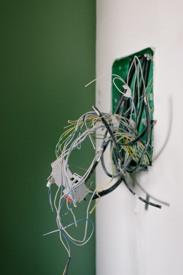
🍀 Advantages
- Automated moisture extraction without relying on occupant memory to turn on fans.
- Substantial reduction in bathroom wall condensation, tile grout mold, and mirror fogging.
- Seamless integration into existing wall switch plates using double-rocker switches.
🔻 Weaknesses
- Requires running additional electrical conductors through wall conduits to the switch.
- Slightly higher fan noise levels while the bathroom light remains switched on.
Before going further, you need to understand what happens when you connect a single-flow ventilation system to a light switch. The idea is often to activate the ventilation only when someone turns on the light, for example in the toilet or bathroom. Result: no unnecessary noise when no one is there, but effective air extraction when the room is in use.
This ventilation connection is tempting, but several technical details quickly come into play: ventilation speed (one or two speeds), type of switch (single or double), and also the electrical power circuit. Let’s talk about it openly!
⚠️ Common mistake: Forgetting to pull a neutral wire (blue conductor) to the light switch box when installing a timed VMC relay module. Electronic timer modules require a permanent neutral connection to operate properly.
What impact on ventilation and comfort?
💡 Practical tip: Use color-coded wire labeling or marked lever connectors (Wago) inside flush-mounting back boxes. Distinctly labeling permanent live and switched live wires prevents short-circuit errors.
Synchronizing the ventilation with the light reduces energy consumption and lowers noise when the room is empty. That said, depending on use and configuration, the ventilation can sometimes be insufficient. Some then prefer a timer – but that already complicates the installation a bit.
By keeping the ventilation connected to the light switch, you gain simplicity and daily electricity savings, especially if your model is basic and does not require multiple speeds.
| Control configuration | Wiring complexity | Moisture extraction efficiency | Safety compliance level |
|---|---|---|---|
| Switched live to VMC boost speed | Medium (4-wire cable needed) | High (Instant boost upon lighting) | High (2A dedicated breaker) |
| Timer delay relay switch | High (Requires timer module) | Maximum (Runs post-light shutoff) | High (Standard bathroom zone) |
| Dedicated 2-speed rocker switch | Low (Independent control) | Medium (Requires manual user action) | High (Direct VMC wiring) |
| Humidity sensor automatic switch | Medium (Integrated hygrostat) | Maximum (Self-adjusting fan speed) | High (Sensor automated) |
What are the risks for electrical compliance?
The NF C 15-100 standard clearly specifies that each circuit must meet certain constraints: wire gauge, presence of a dedicated circuit breaker if needed, and clear separation between functions. Directly connecting the ventilation to the lighting circuit will only be compliant if the total load does not exceed authorized limits and if any intervention remains easy to identify.
Hence the importance of carefully checking the condition of your existing installations before starting the ventilation connection. You wouldn’t want to get into trouble because a wire was too old or poorly insulated behind the wall…
To explore further, I recommend reading our guide on understanding electrical panel breaker sizing for home safety standards. Checking our advice on preventing mold stains from indoor condensation highlights the importance of adequate ventilation. And to go even further, discovering electrical installation best practices ensures clean wiring conduit routing.
Wiring diagram to connect a ventilation system to a light switch
The wiring diagram depends notably on the number of speeds on your ventilation system and the type of control you want. Don’t worry, even if you’re starting from scratch, a few tools and a minimum of organization are enough.
Here’s how to proceed step by step, without any unpleasant surprises. As a bonus, I add a small list of common mistakes to avoid the classic blunders of a hurried DIYer.
Parallel connection: instructions
To connect a single-flow ventilation system to a light switch, one generally opts for a parallel connection. This means that the power supply will simultaneously reach the light and the ventilation motor as soon as you operate the switch.
Specifically, you need to carry out the following operations:
- Tap the phase wire arriving at the light switch.
- Connect a second wire from the switch output to the control terminal of the ventilation system.
- Connect the neutral from the lighting circuit to the ventilation system.
- Provide a ground wire if necessary (depending on model and room classification).
- Ensure that the dedicated circuit breaker properly protects the entire setup.
With this wiring diagram, you ensure a clear, reliable, and safety-compliant installation.
Special case: two-speed VMC and changeover relay
If your VMC offers two speeds, you must include a changeover relay. This device allows you to choose between the low cruising speed (continuous ventilation) and the high speed (when you turn on the light, so when the room is in use).
In this case, the wiring diagram includes more wires: one for the low speed (permanent), another for the high speed (controlled by the light switch or via the changeover relay), and of course the neutral that connects everything. A quick check of the manufacturers’ manuals often confirms this basic principle.
Some precautions to take on a lighting circuit
Handling a lighting circuit to add a VMC connection is never trivial. Beyond the aspect of compliance with NF C 15-100 standard, you have to think long term: ease of maintenance, traceability, and above all no unexpected overload on the dedicated circuit breaker.
A simple tip: label your panel to indicate the VMC connection added to the lighting circuit. The next DIYers – including you in five years – will thank you warmly!
Detect and avoid the most common pitfalls
A classic problem is underestimating the length or gauge of the wires needed to run a new line to the VMC. Always take an extra meter, and prefer quality wire connectors or Wagos for the connections.
Never neglect polarity or proper wire identification when reassembling the light switch. You think you’re saving time… then end up dismantling everything because the light no longer turns on or the VMC runs continuously.
Site tip: better safe than sorry
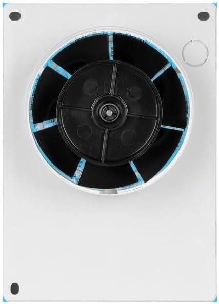
On my first jobs, I often forgot to test each step with a multimeter to check for absence of voltage and proper current flow. Since then, it’s become automatic: main switch off, test, connection, re-test. A time saver in the end, believe me!
Also don’t hesitate to take advantage of the technical hatch to neatly slip in the new cables, and make sure nothing gets pinched when reinstalling the equipment. Making a new hole in the drywall just to fix a cable is frustrating…
Ultimately, successfully connecting the VMC to the light switch requires good preparation, respect for electrical safety, and a careful eye on compliance with NF C 15-100 standard. Whether you prefer an all-in-one solution or the sophisticated setup with changeover relay and multiple VMC speeds, remember that the key lies in mastering your wiring diagram and taking care of the lighting circuit involved.
VMC wiring cable & accessories estimator
Estimate required cable length and electrical accessories based on conduit distance.
Recommended 4-core cable to purchase:
Meters
Estimated hardware expenditure:
$
Everyone has their habits, but over time, it’s this rigor that makes the difference between a reliable installation and recurring minor problems. If you hesitate, take the time to observe, track progress day by day, and above all: never skip steps. The joy of DIY is also that — learning, correcting, and sharing your tips to help others avoid repeating the same mistakes!