ol.mg-steps{list-style:none!important;counter-reset:mgstep;margin:1.6em 0;padding-left:0!important}ol.mg-steps>li.mg-steps__item{counter-increment:mgstep;list-style:none!important;padding-left:0!important;padding-bottom:1.4em}ol.mg-steps>li.mg-steps__item:last-child{padding-bottom:0}ol.mg-steps>li.mg-steps__item>:last-child{margin-bottom:0}ol.mg-steps>li.mg-steps__item>.mg-steps__title{margin:0 0 .25em;font-weight:600}ol.mg-steps>li.mg-steps__item>.mg-steps__title::before{content:counter(mgstep) “. “;opacity:.45;font-weight:500;font-variant-numeric:tabular-nums}ol.mg-steps>li.mg-steps__item:not(:has(.mg-steps__title))::before{content:counter(mgstep) “. “;opacity:.45;font-weight:500;font-variant-numeric:tabular-nums}.mg-kpis{display:grid;grid-template-columns:repeat(auto-fit,minmax(140px,1fr));gap:14px;margin:1.5em 0}.mg-kpi{padding:1em .9em;border:1px solid #e5e7eb;border-radius:12px;background:#f9fafb;text-align:center}.mg-kpi__value{display:block;font-size:1.7em;font-weight:800;line-height:1.15;color:#111827}.mg-kpi__label{display:block;margin-top:.35em;font-size:.85em;color:#6b7280;line-height:1.35}
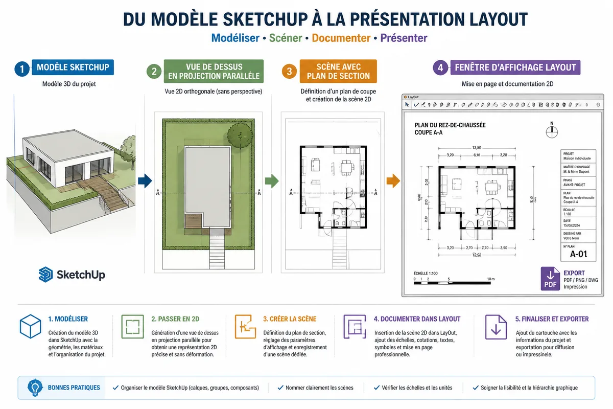
To draw a 2D plan with SketchUp LayOut, prepare a top view in parallel projection in SketchUp, ideally with a scene and a section plane, then send the model to LayOut. In LayOut, insert the scene, set the scale and viewport, add dimensions and annotations, then export the document in the appropriate format.
The expected result is not simply a flattened view of your model: it is a readable, dimensioned, and transferable sheet for a house plan, apartment, interior layout, or renovation. The trap rarely lies in drawing a wall; it appears when a scene is poorly saved, a cut is invisible, or an automatic framing distorts the final document.
| 📐 | SketchUp function: to build the actual geometry of walls, openings, partitions, and fixtures. |
| 📄 | LayOut function: to compose the sheet, the model window, the dimensions, texts, and title block. |
| 👁️ | Necessary view: a top view in parallel projection to remove perspective. |
| ✂️ | Useful cut: a section plane allows showing walls and openings as on a floor plan. |
| 🧱 | Organization: groups, components, and tags separate geometry from display elements. |
| 📏 | Final document: a fixed scale, readable dimensions, and a filled title block. |
| 📤 | Output: the export format depends on the edition and version used; LayOut and SketchUp do not necessarily offer the same outputs. |
What is the role of SketchUp and LayOut in a 2D plan?
SketchUp builds the project in three dimensions, even if you only draw a plan viewed from above. LayOut then transforms a model scene into a documented sheet with scale, dimensions, and annotations. But LayOut will not fix poorly organized geometry: the quality of the sheet primarily depends on the SketchUp file.
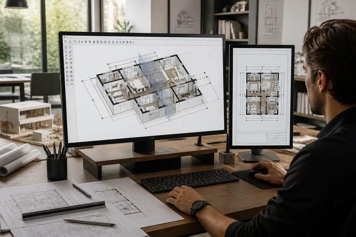
SketchUp is suitable for drawing exterior walls, partitions, doors, windows, stairs, and furniture. The Line, Rectangle, Offset, and Tape Measure tools allow building with real dimensions. A tutorial example uses a length of 800 mm as direct input after drawing; this value illustrates the method, it obviously does not fix the length of a wall.
LayOut then receives the SketchUp file or the model sent from it. The page contains a viewport linked to a scene, while dimensions and texts can be placed on the sheet. The geometry must remain in SketchUp, the presentation information in LayOut. This separation avoids turning the model into an annotation panel that is difficult to maintain.
Direct 2D drawing in SketchUp remains possible for a simple sketch or a quick survey. For a document intended for a craftsman, a project manager, or a clean print, going through LayOut is the appropriate choice: it provides a page, a scale, and a graphic hierarchy to the drawing. A 2D plan for communication must be understood without constant oral explanation.
Prerequisites before starting
You need a clean SketchUp file, an edition that provides access to LayOut, and a clearly defined document objective. An interior layout plan does not require the same density of information as a plan intended to describe partitions or openings. A LayOut sheet template can range from A4 to A0 format in presentations dedicated to this layout.
- Prepare the known dimensions of the project and choose a consistent unit.
- Decide whether the document will show only the walls, a furnished plan, or multiple technical categories.
- Keep the SketchUp and LayOut files in the same working folder.
- Plan a file name that distinguishes the model, the scene, and the exported sheet.
How to prepare the SketchUp model for a 2D plan?
Start by building closed and grouped shapes, then prepare a top view in parallel projection. Walls, openings, and equipment must be identifiable separately before any layout. This way, a partition modification does not catch a neighboring face nor move a piece of furniture left in the raw geometry.
First create the exterior footprint with connected lines. Then use Offset to get a regular thickness or draw the interior boundaries when the project requires particular shapes. A partition illustrated in a guide measures 70 mm, i.e., 7 cm; keep this value as an example of millimetric input, not as a universal construction thickness.
Each coherent set must be converted into a group or component. Exterior walls, partitions, joinery, furniture, and equipment must not remain mixed edges and faces. A component is useful when several elements repeat; a modification on its definition can then propagate to its occurrences.
Tags are used to control visibility, not to fix poorly grouped geometry. Leave the active geometry in the appropriate group, then assign the groups or components to the tags that correspond to their category. This organization allows preparing a general plan scene, a furnished scene, or a simplified scene without deleting objects from the model.
However, do not place the main dimensions in SketchUp if they are only to be used on the sheet. Model-specific dimensions can help during drawing; presentation dimensions will be easier to align and hierarchize in LayOut. For a plan drawn without installation, online tools may suffice; comparing with a 2D plan created for free online helps measure what LayOut really brings: documentation linked to the model.
Top view and parallel projection
In SketchUp, select a camera view located above the project, then activate parallel projection. These two settings remove line convergence and provide a usable representation for a plan. A perspective view distorts apparent distances and is not suitable for a dimensioned sheet.
The north direction, if useful for the file, must be consistent with the orientation chosen in the model. Do not rotate the sheet to get a prettier presentation afterward without keeping a clear reference: facades, openings, and parcel boundaries risk being misinterpreted.
Create a section plane
A section plane virtually cuts the model at a chosen height to show walls and openings as on a floor plan. Place it horizontally and observe what it actually cuts. A door located below the section plane may appear, while an element too high or too low disappears.
The section does not replace the top view; it sets the height at which the model is read. If a window does not appear, start by examining its position relative to the section plane, then the state of the tag that contains it. No need to redraw the opening before identifying this masking.
How to create a plan scene in SketchUp?
A scene records the top view, parallel projection, visible elements, and graphic style intended for LayOut. Create it when framing and section are ready, then use this scene as the display window reference. But a scene is not a frozen image: it remains linked to the model and can change after a modification.
Give the scene an explicit name, for example “General plan,” “Furnished plan,” or “Level 1 plan.” A vague name like “Scene 3” quickly becomes unusable as soon as several sheets and levels enter the folder. The scene must remind what it shows and not the order in which you created it.
Then adjust the display style. Sharp outlines, sufficiently contrasted faces, and visible cut elements facilitate reading. Photorealistic textures and decorative shadows generally weigh down a technical plan; keep them for a presentation view, not for a sheet intended to be dimensioned.
For a file with multiple levels, create a scene for each level or usage. A general plan scene can show the walls and circulation paths, while a layout scene displays the furniture. The same scene should not try to carry all the information: it would become unreadable in LayOut.
And don’t forget the orientation of the sheet. The top of the view must correspond to the orientation chosen for the project, unless a rotation is explicitly indicated by a north arrow or an equivalent indication.
How to send the SketchUp model to LayOut?
Save the SketchUp model after creating the scene, then use the send to LayOut command when it is available in your edition. LayOut then opens a sheet containing a window linked to the model. If you start from an existing LayOut document, insert the SketchUp file into a model window and then select the prepared scene.
Step 1: save the source model
Save the SketchUp file before transferring. The LayOut document must be able to find its source model, otherwise the window will show a broken link or an old version of the drawing. Place both files in a stable location and avoid renaming the model in the middle of the layout process.
Step 2: send or insert the file
Launch LayOut from SketchUp or open LayOut to insert the SketchUp file. Choose the document template corresponding to the desired sheet format, then place the window on the page. Do not try to adjust dimensions before selecting the correct scene: a dimension placed on a provisional view will have to be redone.
Step 3: select the prepared scene
In the display window properties, select the scene dedicated to the plan. The window must show the planned top view and section, without perspective. If LayOut shows another view, the problem is usually in the chosen scene or in the fact that the window properties were modified after insertion.
LayOut can be used for several sheets from the same file. A modification of the walls in SketchUp can update the linked windows, while the texts and layout remain in the LayOut document. Save both files regularly: a single file is not enough to preserve the entire work.
How to adjust the display window and scale in LayOut?
The display window must show the complete scene without perspective and at a readable scale. Select the scene, choose a fixed scale when the document is intended to be printed, then adjust the framing inside the window. Resizing the frame should not cause an automatic adjustment that changes the intended scale.
For a general plan, give enough space to walls, circulation, and openings. For an interior layout plan, the furniture may require a larger window or a wider sheet. A tiny drawing on a sheet that is too large is not more professional; it simply forces the reader to look for a magnifying glass.
Zoom and scale do not have the same role. Zoom determines what the window contains; scale indicates the representation ratio on the page. After a framing change, the displayed value must remain the one suitable for the document. If it switches to fit-to-window mode, the sheet is no longer controlled for printing.
For a printed document, choose a scale that allows texts and dimensions to remain readable. Do not promise greater accuracy than the dimensions actually entered in the model. A dimension displayed with many decimals does not make an approximate survey more accurate.
But locking the window only occurs after framing. Lock it when the scene, scale, and visible content are correct; this will prevent accidental movement while adding annotations. To modify the view later, deliberately unlock the window, change the framing, then restore the fixed scale.
How to add dimensions, annotations, and title block?
Add dimensions in LayOut when the sheet needs to present consistent and easy-to-modify measurements. Start with the general dimensions, then place the useful lengths of walls, rooms, and openings. Thus, the dimensioning describes the project without overlapping doors, texts, or important symbols.
General dimensions are often placed outside the plan’s footprint. Interior dimensions find their place inside rooms or along partitions, with enough spacing to distinguish each line. Do not dimension every segment by reflex: a forest of numbers hides useful information.
Add room names with simple and regular texts. Labels can designate a door, a window, or equipment, while a legend specifies a material or a planned intervention. Hatches, symbols, and purely graphic details are often cleaner when they remain in LayOut rather than being integrated into SketchUp geometry.
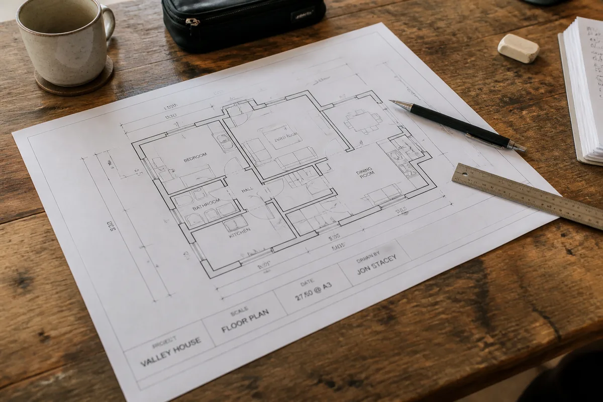
The title block must identify the document. At minimum, enter the project name, the plan title, the date, the scale, and the sheet number when the folder contains several. Add the name of the level or area represented: “floor plan” provides more information than a simple “2D plan“.
A hierarchy of lines facilitates reading. Cut elements can be more prominent than elements seen in the background; furniture must remain identifiable without overpowering the walls. A good sheet does not show everything with the same graphic strength. It guides the eye towards the structure, then towards the necessary details.
- Place general dimensions before secondary dimensions.
- Space dimension lines away from walls when space allows.
- Keep a constant text size for rooms and markers of the same level.
- Reserve long annotations for a legend or a dedicated area.
- Do not cover an opening with an arrow or a label.
The final plan often serves to explain a renovation. For a partition, a door location, or a distribution modification, a clear dimension is better than a seductive rendering. Readers looking for simpler software can also compare uses with a free easy 2D house plan software, but the logic remains the same: readable geometry, identifiable measurements, and an unambiguous document.
How to export and check the final 2D plan?
Before exporting, check the dimensions, scale, openings, title block, and visible elements in the window. Then, export from the software that actually carries the layout, usually LayOut for a documented sheet. The available format depends on the edition and version; specialized articles notably mention PDF, JPEG, PNG, TIFF, or DWG in different contexts.
Start by comparing several displayed dimensions with the measurements entered in SketchUp. A repeated error on a single room often reveals a bad tracing; a global error rather indicates a scaling or framing problem. The dimension value must correspond to the model, not the apparent size of the window.
Then examine the sheet at its output size. A cut title block, a covered annotation, or a line too thin may seem acceptable on screen and become unusable on paper. Texts must remain readable without excessive enlargement, especially if the sheet is intended to circulate among several stakeholders.
Export a first control version before the final version. Open the obtained file and look at page boundaries, fonts, dimension lines, and imported elements. If the result does not match the LayOut sheet, correct the source rather than manually retouching the exported file.
However, do not delete source files after export. The SketchUp model carries the geometry; the LayOut document carries the sheet, windows, and annotations. A correction of a partition or opening must be able to return to the source file without having to rebuild the entire sheet.
Common errors in SketchUp and LayOut
The most common blockages come from confusion between view, section, scene, and display window. A correct scene can be displayed with a wrong tag; a well-set window can lose its scale after resizing. Yet, each failure leaves a precise clue and is handled in order, without redrawing the entire project.
The view remains in perspective
A perspective keeps lines converging towards the horizon and makes distances difficult to read. Return to the top view, activate parallel projection, then save the scene with these settings. Do not try to compensate for a perspective by simply enlarging the window.
Walls or doors disappear
An absent element may be placed on a hidden tag, located outside the section plane, or covered by a face. Display the relevant category, check the cut height, and observe the geometry in SketchUp before modifying LayOut. A door that is not cut by the section plane will not behave like a cut wall.
The scale changes after framing
The fit-to-window mode prioritizes filling the frame rather than maintaining a printable scale. Select a fixed scale, adjust the window content, then lock it. If the frame needs to change, do so before finalizing the sheet.
Annotations cover the drawing
An annotation added too early can hide an opening or an already placed dimension. Move it to a free area, reduce its length, or create a separate legend. Do not reduce the entire board to fit a single text: shortening the text is often the proper correction.
The LayOut file does not reflect the modification
The window may display a different scene than the one modified in SketchUp, or the source file may have been moved. Save SketchUp, refresh the LayOut document, and check the link with the correct model. Sheet annotations should not be recreated simply because the geometry has changed.
A common misconception deserves to be debunked: “just export a screenshot of the top view.” A screenshot rarely preserves a usable scale, does not provide a clean title block, and mixes the drawing with the software interface. For a personal sketch, this is acceptable; for a transferable document, it is not.
Best practices to keep a plan clean after modification
Maintain a stable structure from the first drawing: separate groups, reusable components, named tags, and dedicated scenes. This organization allows updating multiple sheets without losing presentation information. And it makes the file understandable when you return to it several weeks later, which happens more often than one would like.
Use names that describe the content, such as “Walls,” “Openings,” “Furniture,” or “Level 1 Plan.” Names should remain consistent between scenes and LayOut windows. A category that changes name or role during the project makes troubleshooting unnecessarily difficult.
For project variants, duplicate the scene or the sheet rather than modifying a validated view without keeping the old one. This way, you can compare the existing and the proposed, or distinguish a demolition plan from a layout plan. 2D details specific to a sheet remain in LayOut; elements that actually describe the building remain in SketchUp.
The simple version consists of producing a single scene, a single window, and a sober title block. The clean version adds scenes by level, readable tags, appropriate styles, and separate sheets for different uses. In both cases, the rule does not change: the document must allow another person to understand what each line means.
FAQ on drawing a 2D plan with SketchUp and LayOut
How to print a plan created in LayOut?
In LayOut, use the print command to choose the printer, paper size, and sheet orientation. Keep the document scale and disable automatic page fitting if you need to respect a precise scale.
Which format to choose to transmit a LayOut plan?
PDF is suitable for transmitting a finalized sheet, as it preserves the page layout, texts, dimensions, and title block. An image can serve as a preview, but it is less suitable for scale printing.
How to organize multiple levels in the same LayOut document?
Create a separate page for each represented level or area, with a display window linked to the corresponding scene. Use the same title block and presentation logic so that the sheets remain consistent in a multipage folder.